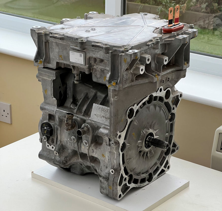


After a lot of research into motors, we decided to fit a Nissan Leaf EM57 motor with a ZE1 inverter. The later (2018 onwards) Nissan Leaf ZE1 motors can deliver up to 160kW/215bhp, 340Nm torque and spin to 11,300rpm. They feature an removeable inverter and a liquid cooling system that runs through both the inverter and motor (in series).
We purchased a motor and inverter in very good condition and with just 5281 miles on it. The Nissan Leaf charging unit was fitted on top of the inverter but we removed it as we have no plans to use it.

The inverter sits on top of the motor, with the charger then sitting on top of the inverter. They feature a common cooling system, with each module linked in series.
We have purchased the EM57 motor and standard ZE1 inverter (3rd generation Nissan Leaf). This is the 110kW (149bhp) / 320Nm version and spins to 10,390rpm. The Nissan Leaf e+ model has an uprated inverter giving 160kW (215bhp) / 340Nm and spins to 11,330rpm. To make installation easier in the space available, the inverter can be unbolted and remotely mounted. There is a great YouTube video by Benjamin Nelson showing the disassembly.
It is also easy to fit an Nissan Leaf Gen 2 'open inverter' controller to achieve 136kW (182bhp) / 350Nm.
We have run a seperate 12V dc power line to the inverter, via its own 3A fuse. Our measurements show that it took about 0.5A on standby and about 0.9A when in use.

Pictures don't really show how compact this unit is. The EM57 motor measures 320mm at its widest point and is 317mm tall. From the centre of the shaft to the lowest point is 134mm.
The ZE1 inverter measures 350mm at its widest point and is 103mm tall. The locating studs on the top stick out another 13mm. The power connection tabs stick out 56mm.

The EM57 motor is 310mm deep and the shaft sticks out 55mm.
The ZE1 inveter is 375mm deep.
We are going to need to fabricate custom motor mounts.

In order to test the motor, we fitted a temporary cooling system and this will include all the sensors too. Once we have the engine located in the car, we will swap this cheap hose out with proper silicon hoses. It is also only rated to about 70°C.

For the MX-5e we are using the Vehicle Control Unit (VCU). There is a great YouTube video by Benjamin Nelson showing the Vehicle Control Unit (VCU) being used to bench test our chosen motor and inverter. It also supports quite a few useful features, including regenerative braking. This is described in a lot more detail on a dedicated Vehicle Control Unit (VCU) page.
The existing petrol engine an automatic gearbox in the MX-5e are removed, along with the existing propshaft.
Our proposed transmission design gives a top speed of 103mph when using the 110kW motor, which spins to 10,390rpm.

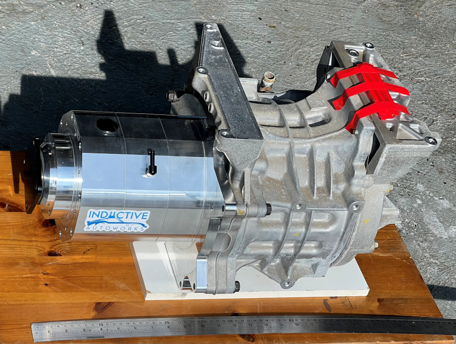
A reduction box is used to lower the high rotation speed of the motor (10,000+rpm) to something more useful. The fixed ratio reduction gearbox is bolted to the motor using an adaptor plate. We are using a fixed ratio reduction gearbox by Inductive Autoworks fixed to the output shaft of the Nissan Leaf motor, with a 1.8 : 1 reduction ratio.
We will use a custom propshaft to mate the reduction box to the differential.
Our MX-5e started out as a 1992 Eunos Roadster. This model year features the weaker 6" differential found on early MX-5s. We plan to upgrade this to a later 7" differential and this will require newer drive shafts too. This differential is good for about 400bhp. This also gives us the opportunity to change the diff ratio to something more optimal to our needs and we will also fit a brand new limited-slip differential internals, to better handle the power and torque.

This is the connector on our (3rd generation) inverter. When we looked through the detailed documentation provider by ThunderStruck Motors we couldn't find any diagrams that matched it.

A quick email to ThunderStruck Motors support and we got this table back very promptly.

Whilst the table is incredibly useful, you still need the Nissan drive harness to connect the inverter to the motor connector, which has position sensors (resolvers) and also an in-built motor temperature sensor. The harness also connects the coolant temperature sensor. There are also some shielded cables inside this harness, so I'm not sure if building your own would work very well.

We stripped the protective tape and plastic from the harness, to better understand how it is all wired up. The plan being to strip out all of the redundant wires and connectors. The only bit of this harness we need to use is circled in red.

With the harness stripped back to bare wires, we could plug it into the inverter and see what colour wires went to each pin. We then cross-checked all the pins with the table sent to us by ThunderStruck Motors. It aligned really well, with just a couple of wires being different colours but clearly serving the same function.

Most of the harness is redundant to our needs. All of the wires and connectors you can see here are not needed. There are just a few wires that need to be connected to the bits of the harness that are used:
CAN-H (green) and CAN-L (blue) are the CAN Bus connections. Both the inverter and Vehicle Control Unit (VCU) are connected and other devices, such as a dc-dc converter may also share the CAN network.
Normal CAN network wiring guidelines should be followed. Wiring should be kept short and the conductors should be twisted. Wiring should be placed away from electromagnetic interference such as the motor and parallel runs next to EV traction cabling should be avoided.
The CAN Bus must be terminated on both ends of the string by 120Ω termination resistors. Wiring stubs to non-endpoint nodes should be kept as short as possible, ideally less than a few inches. The Vehicle Control Unit (VCU) contains an internal, configurable, termination resistor, enabled by default but can also be disabled in software.

In order to test the high-voltage side and the motor, we are using a 1000V (full wave) bridge rectifier to rectify 230V ac mains power and acts as our battery. This gives a peak dc voltage of about 325V and an average dc voltage of about 207V. It is enough to get the motor running.

We purchased this throttle pedal from ThunderStruck Motors. It is a HXWJ-04-0000(22) Hall effect throttle, with an input voltage of 14 - 90V dc ± 2%, signal output is 0 - 5V dc (0.2 - 4.9V ± 0.1V). Working current is (20mA max). Pedal stroke angle is 17.5° ± 2°.
This throttle also has a binary switch output but this is not currently connected.
We have recorded a few videos of the Nissan Leaf motor on our test bench. You can find these in the media section and on our YouTube channel.