


This project is to develop the digital instrument display that sits behind the steering wheel in both the MX-5e and the OSSEV®.
Note that this is in addition to the 3rd party screen being used for entertainment and navigation.

The goal is to replace the MX-5e instrument cluster behind the steering wheel with a solution that also works brilliantly in the OSSEV®. This MX-5 cluster is white and is installed in Yoko. We don't really want to do this job twice, so any thoughts of retaining or modifying it go out the window. Something that sits within the existing instrument cowling or something similar is an option though.

This is the MX-5e instrument cowling, which we are going to have to re-use if we stick with the standard dash. This one has been cleaned up because it had been painted very badly. We would quite like to add a carbon fibre effect to it.

This is the hole left with the instrument cluster removed and shows the various mounting points. This gives us quite a big space to work with, so we think a common solution for both the MX-5e and OSSEV® is achievable.

This is the instrument cluster removed from our MX-5e and it has white markers on black background. We much prefer this approach (instead of black on white), as it is easier to read during the day and at night. It has a curved glass front and is quite easy to open up, being held together with just a few plastic clips. You can see the (white) mounting points which we are aiming to replicate for now.
As you can see, most of the data shown on this cluster is irrelevant in an EV. The main dials are 92mm in diameter.

This is the back of the MX-5e instrument cluster. Inside are the gauges and and the black covers hold in the 12V bulbs which serve as indicator/warning lights. There are no LEDs in this old school cluster. You can also see the speedometer cable drive entry point.
The digital dash in an EV is very different to a typical ICE car. We don't need a tachometer, fuel level gauge, oil temperature gauge, etc. Mostly we just need to know the current speed and battery level. Many of the key indicators such as lighting state can be LED back-lit icons. Our focus is on an uncluttered instrument cluster that delivers clarity and simplicity. All the information needed will be displayed in a clear and intuitive fashion. We plan to avoid information over-load and keep the focus on pure driver involvement.
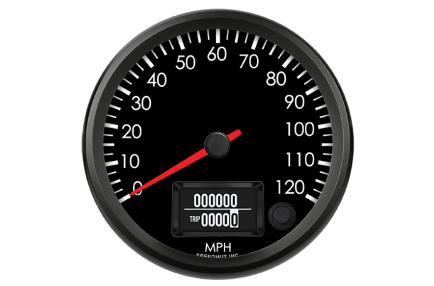
Our initial thinking is that a nice analogue style, digital speedometer with mileometer and trip is the perfect starting point and this can be centrally mounted behind the steering wheel. Everything else can be mounted around this.
Rather than having loads of gauges and information on show all the time, we plan to have a simple OLED/LCD display that reports exceptions. As well as a default view with key data (battery level, range, etc.), it will have a number of information 'screens' that can be selected to show things like:

Our preference is to use a speedometer an mileometer that is driven by a physical speed sensor, rather than a signal from the Vehicle Control Unit (VCU) or the inverter. The main reason for this more simplistic approach is that we are not tied to specific hardware. Given that the MX-5e and OSSEV® are very likely to use different components.
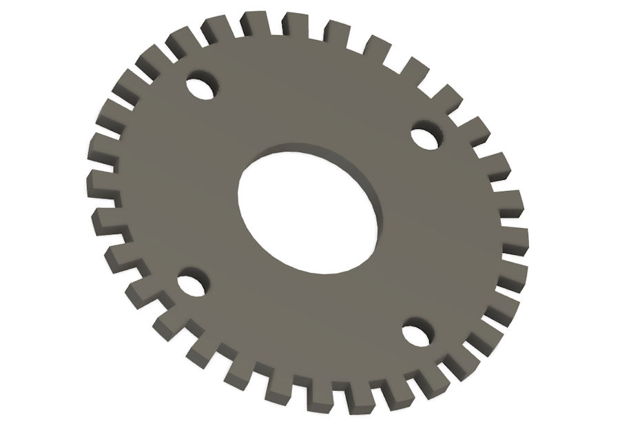
A toothed ring made from a ferrous metal is used to provide the pulses and this can be bolted through to the reduction gearbox output flange or fixed at the far end of the propshaft, as both use the same four M10 bolts on a 96mm PCD.
Our chosen display/sensor combination expects to see less than 250,000 pulses per minute. Given that the output of the reduction gearbox spins at around 6500rpm, then we need a less than 38 teeth on our cogged wheel. Our chosen design has 32 teeth and the STL file is available for download.
The sensor needs to be installed within 0.04" (1.0mm) to 0.06" (1.5mm) of the teeth
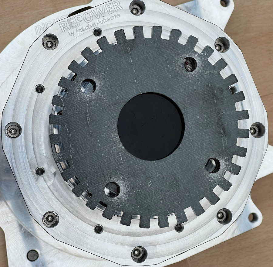
The 5mm steel toothed wheel to drive our speedometer was manufactured by a London-based company for us.
Our starting point is looking at what technology is already out there. Most of the products are aimed at existing ICE vehicles and provide a direct swap for the existing instrument cluster. This means that many of them are configured for ICE vehicles by default and feature things like tachometers and fuel gauges by default.

Arduino processors are simply not powerful enough to drive displays much above 320 × 240 pixels and even then the frame rate will be fairly low because of the underlying SPI or I2C communications used. Using one to simply display basic text and data could work well though. They also come in a wide range of form factors, from square to bar shaped.
We are currently doing some testing with this white OLED 3.12" display with 256 × 64 pixels. It uses an SSD1322 driver IC and SPI interface.

OneGauge sell a product that can fit many vehicles and a variant for the MX-5/Miata/Eunos.
We particularly like the mounting frame and surround used by OneGauge. The surround is there to mimic the depth and shape of the MX-5 instrument cluster and ensure it sits flush with the cowling. We will have to replicate this if we go down a similar route.
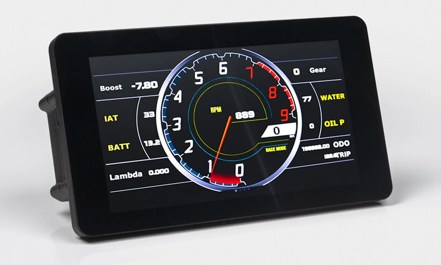
PowerTune Digital sell a range digital displays that can be configured and interfaced to many systems. GPS and data logging are options too.

Speedhut sell a range of EV display and gauges. We particularly like the programmable VSS 120mph 3⅜"/84mm speedometer/mileometer that works with the Vehicle Control Unit (VCU) we are using in the MX-5e but, they support other CAN Bus protocols. It is also available as a larger 4"/100mm version and a 160mph version. It is quite likely that this will be needed in the OSSEV®. All can optionally include high beam LED and direction indicator lights, a GPS speedo or wok with a magnetic speedo sensor
Something like this would be supplemented with a smaller OLED display and custom dash lights.

We are designing the display for the MX-5e in Autodesk Fusion 360 to 3D print it and check our measurements and the ergonomics. In order to fit the OLED display, we have opted for the smaller speedometer option.
Our solution is going to need visual indicators for the following:
Some other visual indicators may also be included within iluminated switches.
We are designing and building our own visual indicators and warning lights, to be an open-source design. These will be LED back-lit graphics and powered by 12V or 5V dc.
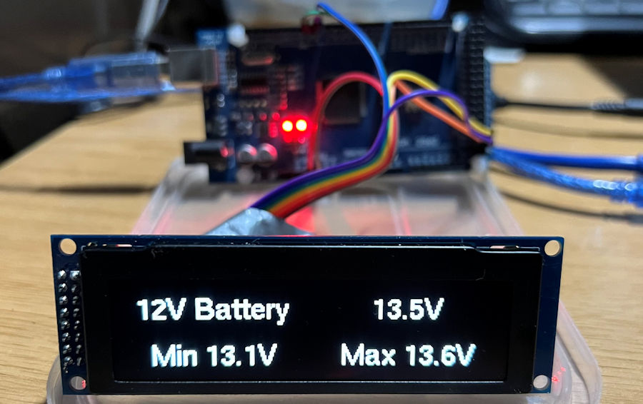
We are making great progress in connecting our chosen OLED display to the Driver Control Unit (DCU). The focus is currently on getting the various fonts and layouts correct, before we look at more advanced features like brightness control and mixed font brightness.
This is the kind of information we are planning to show on the 256 × 64 pixel OLED display:

This is our 'default' display option with 2 rows and 2 columns, allowing 4 data elements on screen at once. The u8g2.getUTF8Width() function allows us to calculate the width of the text to be displayed and thus centre it in each column. It uses a Helvetica font that is 14 pixels high, to ensure we can display enough characters on screen.
Because our preferred speedometer displays only mph, we can also use the default view to display the speed in kmh (instead of the clock or outside temperature). A dual mph/kmh display is sometimes needed for UK vehicle tests.
These are the exit temperatures of the coolant from the battery
The U8G2 library that I'm using olny supports monochrome, so I can use different grey levels for the fonts. I can use both regular and bold fonts though.
We can display some of the more unusual characters required (e.g. degree symbol °) by using the u8g2.enableUTF8Print() function and the u8g2.drawUTF8() function to render text.
We can easily centre text in various areas of the screen by using the u8g2.getUTF8Width() function to predict how many pixels are used for the chosen text and font. This is accurate to within 1 pixel.
We are able to set the display brightness using the u8g2.setContrast() function. This uses a value from 0 (off) to 255 (maximum brightness) and even a value of 8 is perfectly legible as the OLED blacks are very black. Lower contrast/brightness also uses less power.